Spoofer IR per decoder TV

Problema da risolvere: genitori che si dimenticano di spegnere il decoder quando spengono la TV

Soluzione? Uno spoofer sul ricevitore infrarossi del decoder che, alla ricezione del comando per accendere/spegnere la TV, inietta al decoder il suo comando di accensione/spegnimento.

Materiale necessario:

  • Per lo spoofer: un microcontrollore Attiny85, un socket DIP8, un jack audio 3.5mm maschio
  • Per la programmazione: una scheda Arduino Uno (o simili), un ricevitore infrarosso, una breadboard e relativi cavetti di collegamento

Veniamo al sodo: i telecomandi infrarosso trasmettono una serie di impulsi, modulati tipicamente a 38 kHz, che trasportano alcuni byte di informazione e che i dispositivi comandati interpretano, agendo di conseguenza. Esistono diversi protocolli di trasmissione, ma la libreria IRRemote di Arduino è in grado di gestirne la maggior parte.

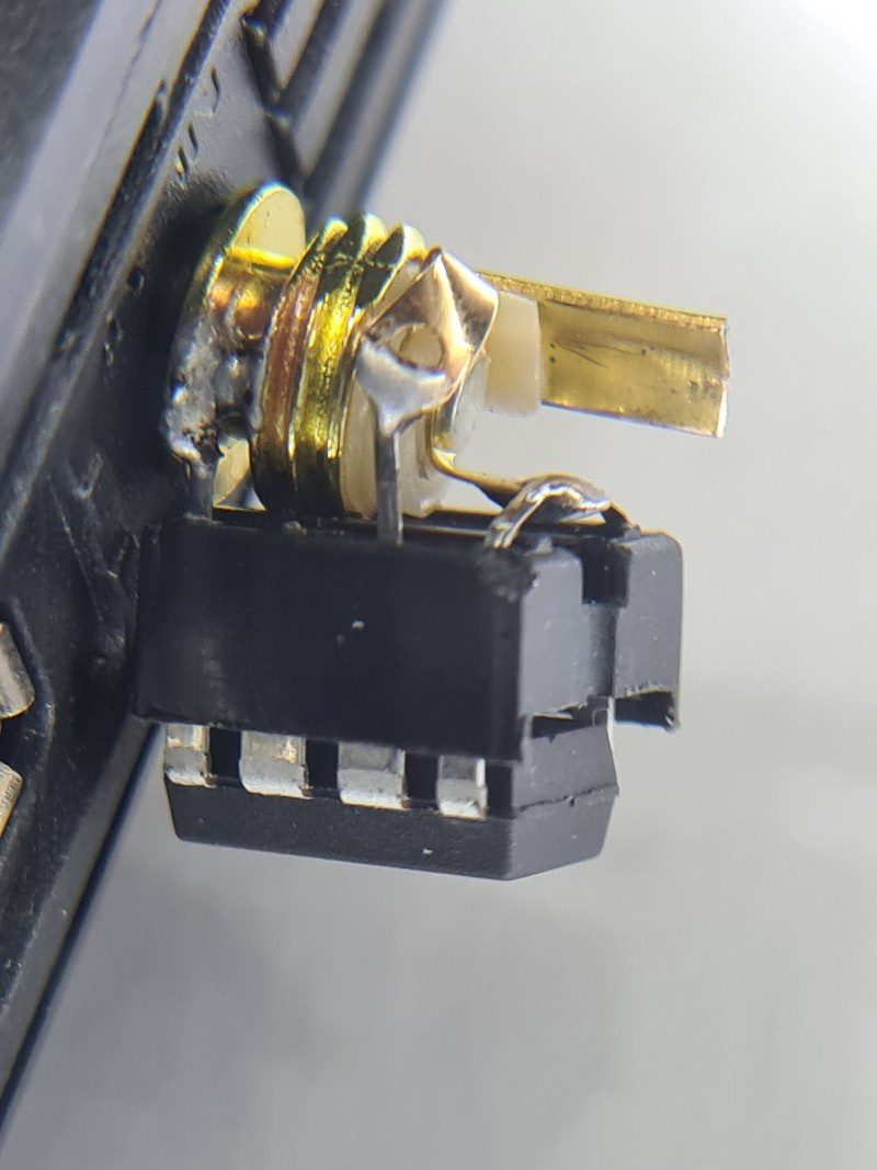
Il ricevitore infrarosso è un componente che riceve il segnale modulato, e lo invia demodulato su una singola linea open-drain. Il decoder in questione ha un ingresso per un ricevitore IR esterno, che è collegato come in figura, ossia in parallelo al ricevitore interno.

Schematico del circuito

Questo ci permette di collegare direttamente un microcontrollore (ho scelto un Attiny85 perchè è piccolo, facile da saldare dato il package DIP e ha sufficiente memoria per lo sketch) alla medesima linea del segnale: esso potrà quindi “ascoltare” la ricezione infrarossa demodulata e, al momento della ricezione del comando “accendi/spegni TV”, che viene ignorato dal decoder, può iniettare sulla medesima linea il corrispondente elettrico del segnale “accendi/spegni decoder”. Inoltre, non si invalida alcuna garanzia perchè non è necessario aprire il decoder o modificarlo in alcun modo: il jack ci fornisce tutto il necessario!

Dopo aver discusso lo schematico, passiamo al codice: ci servirà una scheda Arduino Uno (o qualunque altro Arduino, in realtà) a cui collegare un altro ricevitore infrarosso per capire i due segnali che ci servono: “accendi/spegni TV” e “accendi/spegni decoder”. Per farlo possiamo usare l’esempio “IRrecvDump” collegando un ricevitore infrarosso al pin 11, alimentandolo da +5V e GND della scheda Arduino. Carichiamo lo sketch, apriamo il monitor seriale e premiamo il tasto sul telecomando che ci interessa: il microcontrollore ci dirà il protocollo di codifica, il comando e il numero di bit (“Decoded NEC: 807F807F (32 bits)” e “Decoded NEC: 20DF10EF (32 bits)” nel mio caso, per il tasto di accensione della TV e del decoder, rispettivamente). Prendiamone nota.

A questo punto possiamo passare al codice per l’Attiny: seguiamo questa guida selezionando però un clock “16 MHz internal” per l’Attiny. Scarichiamo inoltre la libreria tiny_IRremote e mettiamola nella cartella delle librerie di Arduino per poterla utilizzare. Riavviare la IDE per renderla disponibile e utilizziamo il codice seguente:

#include <tiny_IRremote.h>

#define NEC_BITS          32
#define NEC_HDR_MARK    9000
#define NEC_HDR_SPACE   4500
#define NEC_BIT_MARK     560
#define NEC_ONE_SPACE   1690
#define NEC_ZERO_SPACE   560
#define NEC_RPT_SPACE   2250

int RECV_PIN = 3;
int TX_PIN = RECV_PIN;

IRrecv irrecv(RECV_PIN);

void sendwire(unsigned long data,  int nbits) {

  pinMode(TX_PIN, OUTPUT);
  noInterrupts();
  //Header
  digitalWrite(TX_PIN, 0);
  delayMicroseconds(NEC_HDR_MARK);
  digitalWrite(TX_PIN, 1);
  delayMicroseconds(NEC_HDR_SPACE);

  //data
  for (unsigned long  mask = 1UL << (nbits - 1);  mask;  mask >>= 1) {
    if (data & mask) {
      digitalWrite(TX_PIN, 0);
      delayMicroseconds(NEC_BIT_MARK);
      digitalWrite(TX_PIN, 1);
      delayMicroseconds(NEC_ONE_SPACE);
    } else {
      digitalWrite(TX_PIN, 0);
      delayMicroseconds(NEC_BIT_MARK);
      digitalWrite(TX_PIN, 1);
      delayMicroseconds(NEC_ZERO_SPACE);
    }
  }

  //Footer

  digitalWrite(TX_PIN, 0);
  delayMicroseconds(NEC_BIT_MARK);
  digitalWrite(TX_PIN, 1);
  interrupts();
  pinMode(TX_PIN, INPUT);
}

decode_results results;

unsigned long last = 0;
unsigned armed = 0;

void setup()
{
  pinMode(RECV_PIN, INPUT);
  irrecv.enableIRIn(); // Start the receiver
}

void loop() {
  if (irrecv.decode(&results)) {
    last = millis();
    if (results.decode_type == NEC)
  //change according to your remote
      if (results.value == 0x20DF10EF ) {
 //change according to your remote
        armed = 1;
delay(500);
      }
    irrecv.resume(); // Receive the next value
  }
  else {
    if (armed == 1)
      if ((millis()-last) > 500) {
        sendwire(0x807F807F, 32);
 //change according to your remote
        irrecv.enableIRIn(); // Restart the receiver
        irrecv.resume();
        armed = 0;
      }
  }
  delay(100);
}

L’attiny resta in ascolto del segnale infrarosso e, quando protocollo e dato corrispondono al segnale di accensione della TV, il nostro microcontrollore si arma e si prepara a trasmettere il comando di accensione al decoder. Notare che per trasmettere il codice utilizzeremo lo stesso pin che usiamo per la ricezione: aspettiamo quindi 500 ms dall’ultima ricezione prima di trasmettere, tramite “if ((millis()-last) > 500)”. Inoltre, non utilizziamo la funzione “irsend” perchè questa trasmetterebbe un segnale modulato, che andrebbe bene per pilotare un LED infrarosso ma non la linea digitale, dove invece vogliamo il segnale demodulato.

Per trasmettere quindi il segnale demodulato con protocollo NEC sono partito dal file “ir_NEC.cpp” della libreria IRremote, dove si capisce che la trasmissione avviene alternando un ‘1’ di durata NEC_BIT_MARK ad uno zero di durata differente per un ‘1’ e uno ‘0’ digitali (NEC_ONE_SPACE, NEC_ZERO_SPACE”). Quindi ho scritto la funzione sendwire che scrive direttamente ‘1’ e ‘0’ per la durata necessaria sul pin del microcontrollore connesso alla linea di segnale. Notare che, essendo una linea open drain, ‘1’ logico corrisponde alla linea abbassata, quindi la logica è negata.

Per altri protocolli dovreste prendere il rispettivo file ir_PROTCOLLO.cpp (che trovate nella libreria “IRremote”) e riscrivere la vostra funzione di trasmissione. Non è particolarmente complicato: utilizzate i comandi “noInterrupts()” e “interrupts()” rispettivamente ad inizio e fine funzione, perchè altrimenti le tempistiche sono sballate e il segnale non viene trasmesso correttamente.

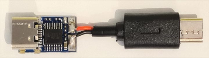
Programmiamo il nostro Attiny e saldiamolo al nostro jack audio maschio con un accrocchio del genere: (io ho utilizzato un socket per permettermi di rimuovere facilmente il microcontrollore per riprogrammarlo).

L’intero circuito saldato sul jack, in modo molto artigianale. Ho lasciato volutamente “lungo” un terminale del jack per facilitare l’estrazione del jack dal decoder tramite una pinza.

Se tutto va bene, alla pressione del tasto di accensione/spegnimento del TV, anche il decoder si accenderà/spegnerà “magicamente”.

Consiglio di isolare il circuito tramite del nastro isolante, del termorestringente, abbondante colla a caldo o una piccola scatola stampata in 3D.

Nota: IL SITO E L’AUTORE NON SI ASSUMONO ALCUNA RESPONSABILITA’ IN CASO DI DANNI DERIVANTI DALLA REALIZZAZIONE E DALL’IMPIEGO DEL CIRCUITO QUI RIPORTATO. LA GUIDA E’ DA CONSIDERARSI A SCOPO PRETTAMENTE DIDATTICO.

DIY USB Type-C charging for Dell Venue 11 Pro 7140

I recently bought a used Dell Venue 11 Pro tablet for online classes. It is a decent windows tablet with Synaptics pen support which makes it possible to write directly on-screen, and it can be bought second hand for < 200€.

I strongly suggest getting the second revision (7140) because it is fanless and has marginally better performance compared to the older model (7130).

The hardware configuration on my machine is decent: 1080p IPS screen, 5th gen Intel Core m3 5Y10c, 4GB of soldered DDR3, 128GB M.2 2260 SATA SSD, Intel 7260 AC WiFi card (2×2) and even LTE support. Plenty for notetaking and online lessons.

The downside of this tablet is that it pre-dates USB-C and thus comes with a weird, proprietary, 19.5 V 1.2 A charger that uses a microUSB port. The tablet can “charge” also form a 5V supply, but only at a measly < 2 W which are not even enough to even keep it topped up when using the device.

Nor the charger nor the tablet itself support any “normal” fast charge protocol such as QuickCharge, meaning that you are forced to use the provided power adapter. The charger outputs 5 V unless the tablet requires the 19.5 V output by juggling the USB D+ and D- lines. However, reports online show that the tablet is fine being fed directly the 19.5 V without the initial handshake.

So…

The information reported below is for your information only and comes with no warranty. It could cause irrepairable damage to your devices and will definitely void any manufacturer warranty. Do it on your own responsibility.

My laptop (Lenovo Thinkpad T480) uses a USB type-C charger that support the Power Delivery (PD) protocol and can provide up to 65 W at 20 V. How nice would it be to bring the Dell Tablet into the 2020s by making it compatible with the USB-C PD protocol, and thus allow me to avoid carrying a different charger?

Well, China got us covered: on Aliexpress/eBay/etc it is possible to find some small, cheap (<2 € delivered) boards that are specifically designed to trigger a PD-compatible charger into providing a predefined voltage (9 V, 12 V, 15 V or 20 V). 20 V is close enough to the 19.5 V specification (a measly + 2.5%) of the Dell Tablet that I figured it should just work.

AND IT DOES.

The tablet is quite happy pulling 20+ W from a 65 W PD adapter.

All you have to do is get a PDC004 20 V board and a whatever-to-microUSB cable: chop the microUSB connector off the cable with whatever length of wire you desire, strip the red (+) and black (-) wires and solder them straight to the pads onto the PDC004 board.

IT’S THAT EASY.

This is the minimal setup, with all the elecrical work required. You might want to keep the cable longer but I wanted a small portable adapter.

BUT!!!! SUPER-MEGA WARNING!

You have just created an adapter that will blissfully provide 20 V to whatever device you plug it into. That means that if you connect this adapter to a device which is not designed to handle the 20 V,

YOUR DEVICE COULD BE OBLITERATED TO DEATH IN MILLISECONDS.

Don’t be a dick: do NOT use this device to prank people. You may easily cause hundreds of euros worth of damage.

You might want to add a warning label to the adapter. I just printed a small enclosure with the warning “⭍ 20V ⭍ ” embossed onto it.

3D printed container with warning label. It’s not pretty, but it’s functional.

Modifica lampada solare “28 LED”

Riprendiamo in mano questo blog riportando una modifica che si può applicare alle lampade solari “28 LED” disponibili su Amazon (varie marche ribrandano lo stesso prodotto: Neloodony e Baxia al momento) per migliorarne il funzionamento in caso non siano esposte a luce solare diretta durante il giorno.

La modifica proposta richiede di avere buone capacità di saldatura, anche di componenti SMD, e richiede 5-10 minuti di tempo.

Partiamo da una breve recensione: queste lampade solari sono di ottima qualità; il pannello solare può fornire comodamente 100 mA se esposto a luce solare diretta, e i 28 LED sono regolati in corrente a 350 mA da un regolatore AMC7135 e forniscono un centinaio di lumen, più che sufficienti ma ben lontani dai 400 lumen “cinesi” dichiarati. La batteria interna è una 18650 con un cavo presaldato, con capacità stimata di 1200 – 1300 mAh, quindi la durata stimata dell’illuminazione è di più di 4 ore.

Il sensore PIR non usa il solito integrato BISS0001 ma è un sensore che integra tutta l’elettronica nello stesso package e ha una uscita digitale, di durata 30 secondi ritriggerabile; buona la sensibilità: si attiva a distanza anche di 4 metri (d’estate la portata è ridotta perchè la differenza di temperatura tra le persone e l’ambiente è minore).

L’unico problema di questo genere di lampade è il sistema di crepuscolare, che è implementato con un grezzo Schitt trigger a bipolari, e che consuma circa 1 mA dal pannello solare: nessun problema se la lampada è lasciata in un luogo dove arriva luce solare diretta, ma se la si lascia in penombra, questo consumo può risultare eccessivo. Ad esempio, testando un pannello solare di simili dimensioni, in penombra esso genera una corrente di 2-3 mA, quindi il trigger riduce la corrente di carica del 33 – 50%.

La modifica che propongo, per quelle lampade che vogliate lasciare in una zona di penombra, è di sostituire il trigger a bipolari con un solo PMOS, in modo da azzerare il consumo del trigger. Continue reading

Blackberry Q10 error BB10-0020 fix (soldering required)

Let’s get quickly to the point: many people have reported that some Blackberry smartphones just randomly refuse to turn on reporting the error “BB10-0020” – here is how I fixed a phone affected by this problem.

Looking on the BB troubleshooting guide, we can see that the error is related to a bad battery, but it typically isn’t solved by simply replacing the battery. Here I will show you how to fix the problem and I will also comment a little bit about what to me appears as an obvious design fault. The problem is due to a broken connection between the battery connector and the mainboard. Continue reading

Syma X5C quadcopter magnetic camera mount hack

Cerchi l’articolo in italiano?

It so happens that I gifted myself a cheap quadcopter for Christmas (although it arrived shortly after New Year) – the Syma X5C, as it has good reviews and is about as cheap as you can go (which also means, there are tons of them around, and replacement parts are widely available and cheap as well). This quadcopter also happens to have an HD camera that, given the price of the whole package, doesn’t suck.

HOWEVER…

The camera mount is not really well-thought. The camera is screwed on the battery compartment lid, at an awkward angle as well. Given that this drone has not much power to spare, flying it without the camera gives both better performance and better runtimes, so I decided that I wanted a better, quicker way of adding or removing the camera as I wished. Continue reading